Hibernation
Matilda is on the hard again for some repairs and the annual maintenance.
 Snow on deck
 And temperatures below zero
 But the next spring is not far away…
Hibernation
Matilda is on the hard again for some repairs and the annual maintenance.
Snow on deck
And temperatures below zero
But the next spring is not far away…
Brief update
Time is short this year, thus only a very brief update. Matilda is of course back in the water and all systems and repairs seem to work fine except of the depth meter which is a bit of a mystery, but I will get that fixed too.
 The mast and all wires and terminals were checked first time after 3 years. There are no problems.
 Halkoutsi home port „aerial“ view from the mast top.

 At anchor in Porto Buffalo bay after a short weekend trip.
Ready to go
There was some additional delay because of the extensive rain last week. The primer could not be applied. Now after the rudder quadrant was remounted the antifouling paint was finished and the engine was tested, Matilda is ready for the water again.
 Waiting for the travel lift
 It was a good feeling finally applying the antifouling on the rudder
Rudder removal and repair – part 3
This operation has not been straight forward but finally the rudder is remounted, hinge and nut covered in putty and the surface faired and ready for the final layers of primer and antifouling.
 The rudder is back in place,
 Hempels Epoxy Light Primer being applied on the removed rudder
 Many layers of Hempels Epoxy Light Primer were applied to the skeg for osmosis prevention (…although judging by the condition of the hull, there is no sign of osmosis)
 Skeg antifouling applied – rudder in the background ready for remounting.
 Finding the right alignment was a bit tricky as can be seen by the bronze plates placed behind the hinge at the skeg. The two pieces at the rudder part (top of hinge) were probably not needed but left there for additional support. The amount of alignment and needed bronze plates will be different for every single HR352. Some won’t need any and others will need what you see above. The good thing is that the rudder works again smoothly as on a Laser dinghy.
 Rudder shaft nut covered in putty again (I have used Plastic Padding Glass Fibre Paste which worked quite well).
 Turniing on the lathe is fun. Here, the washer used for the lower bearing is being made (material is CuSn12).
 Rudder shaft stuffing box – new packing gland applied. The correct size would have been 9mm square. I could only get 8mm square and 10mm square, so I used one 8mm and one 10mm. Both were flattened a bit resulting in one 7X9 and one 11X9
More repairs – part 3
The sailing season has begun and Matilda is still on the hard. I had planned to have her back in the water mid of June but things didn’t develop as desired.
Repair jobs are being completed one after the other though and I am confident that she will be back in the water by Friday the 29th.
Together with the rudder which is also back in place some additional issues came up.
One of the portside portholes was about to fall out of the frame. I had seen this porthole leaking when I sailed back from Milos last year and wanted to re-bed the acrylic window. This is not the only one needing rework but the worst one. The problem is that I was not clear on how to do it properly. The 8mm thick acrylic window sits in an aluminum frame and is mounted from the outside. It is only hold by the silicone that sits in the 3 mm wide space between the edges of the window and the aluminum frame. The area where the backside of the acrylic window touches the frame is silicone free. Everyone (including Hallberg Rassy) was saying that there were better sealing compounds available on the market today than silicone but I also read that if silicone was used once, silicone should be used again. To cut a long story short, I decided to go for what has worked well for so many years. I bought a silicon remover (which seems to be unknown in Greece) and an activator for better adhesion to the acrylic material and tried to do my best. I believe that there are more things that can be done wrong here than right and so, I did only one window as an experiment. I used a UV and seawater resistant silicon.
 After the old silicone was carefully and thoroughly removed and the sealing area was washed and cleaned with alcohol, the activator was applied and the acrylic window was placed into the frame, aligned and hold in place with some pressure ready to for the silicone to be filled into the grove.
 Removing the old silicone from the aluminum frame was the most time consuming operation. It was firs mechanically removed and then the silicone remover was applied. This stuff softens the silicone remains which could then be removed with the help of a square wooden stick. The whole operation is not easy and takes a lot of effort but after half an hour and with the help of a scrub cleaning pad, the aluminum frame was silicone free.
The silicone was applied and it seems that the operation was successful. I can tell this by applying pressure from the inside against the window or by the sound when knocking on it. The question is how long will this last? I hope long. Time will show.
Another problem arose when I was trying to fix the nut that holds the propeller in place. Suddenly it broke into two pieces.

 Judging by the colour, I would guess that this is a clear case of dezincification.
Because of the 3/4” imperial thread, finding a new one for replacement was not an easy task, but I finally found something that suited.
More repairs – part 2
OK, let’s see what’s going on with the other issues.
 Ruder shaft stuffing box body back in place with fresh Sikaflex 291i
Among other things, there was the CENTA coupling, the Volvo shaft seal, the cutlass bearing and the ruder shaft seal. The rudder shaft was leaking a little but not through the packing box. The leakage was between the rudder shaft tube and the fiberglass laminate.
 Stuffing box housing removed from the rudder shaft tube. The sealing at this end was done by the means of silicone which could easily be pealed off.
 A big square pipe was used with two screws welded at the corners for unscrewing the stuffing box housing. It was an easy operation.
 New Volvo Penta propeller shaft sealing installed.
 CENTA AGM Coupling with new rubber part back in place.
 All screws were tightened according to the manufacturer’s instructions using a torque wrench (…of course :-) ).
 Cutlass bearing replaced and remounted. I have sealed part of the internal thread and the contact area to the hull with Sikaflex 291i.
 This ring, is supposed to be used at the location where the rudder shaft exits the hull. Together with some Pantera MS-3000/60 V2 Marine Sealant is should provide proper sealing and solve the leakage problem.
 A groove of 3mm depth was made around the shaft into the hull and the ring was placed into it with some Pantera MS-3000/60 V2 Marine Sealant.
…more to come soon
Rudder removal and repair – part 2
The sailing season 2018 has almost begun and it is time for an update on the ongoing repairs and what has been going on over the past 3 months:
 Making a new pin on the lathe
Back in Germany I reworked the parts of the lower bearing and made a new pin. I used “Essmatur” for the Pin as proposed by Hallberg Rassy in their repair instruction. It took me some time to find out what “Essmatur” was. It is an older Swedish designation for a dezincification resistant brass alloy (DZR brass) much easier to obtain if you ask for CW602N which is essentially a leaded arsenical brass (CuZn36Pb2As). The arsenic provides the dezincification resistance and the alloy is supposed to be suited for applications in seawater environments.
Some dimensions:
 Careful alignment of the hinge parts under the drilling machine ensured that the axis of the enlarged opening remained perpendicular to the contact surface.
 This is the tool that was used to rework the holes.
 My friend and colleague Robert provided some professional help which was highly appreciated!
 The result couldn’t be any better.
 I also made myself some plates (these were made out of Tin Bronze, CuSn12) which I will need for aligning and fixing the position of the bearing to the skeg (the old alignment plates can be seen on the left side of the picture).
Back in Greece I tried putting everything back together. Hallberg Rassy says in the instruction, that a tube must be used for the alignment of the lower bearing if it was removed, in order to get it in line with the shaft axis. I used the rudder shaft upside down together with an adaptor which fitted onto the rudder shaft on one side (40mm) and the (enlarged) hole of the bearing on the other side (36mm).
After some experimenting and a lot of head scratching, I finally had to accept that I would never get the parts aligned as they should be because when they were put together at Hallber Rassy, the lower bearing axis must not have been in line with the rudder shaft axis, but off set by about 5mm. It is of course likely that this is not the first time the assembly is being taken apart, and was not put together properly again.

 The misalignment is obvious
Anyway, some comfort can be derived from the fact that the assembly did work flawlessly for 35 years until I took it apart. I am confident though, that I will find the right position for the alignment plates that I made and get everything back in a proper working order, but first I have to apply some layers of epoxy primer for osmosis prevention since the area is perfectly accessible with the rudder removed.
….more on “Rudder removal and repair – Part 3”
More repairs – part 1
As it seems, I had not enough by just repairing the rudder this winter and so I opened up a few more jobs. There is the cutlass bearing that I will replace and also the Volvo shaft seal but some other problems showed up too.
 The HR 352 has a very classical type of cutlass bearing housing. It can be unscrewed with the help of a large pipe wrench and some effort after removing the two locking screws.
 A polyurethane sealant (Sikaflex 291i?) was used most likely for sealing the bearing housing against the hull but it was also applied on the thread.
The Centa-coupling needs to be disassembled if the Volvo shaft seal is to be replaced. When I started I realized that the water that had entered the boat in Gibraltar in 2015 had led to some corrosion at these parts although I had washed everything with fresh water as soon as I could. It took me about 4 hours to remove the 6 screws fixing the rubber parts to the flanges. One of the 6 screws that hold the rubber parts on the connecting tube wouldn’t let go from the rubber element and so I had to destroy it. That is another EUR 120 for a new rubber element on this season’s list :-)
 These screws gave me a hard time…
 The coupling is out…
 …and so is the propeller shaft from the coupling flange as well as the Volvo shaft seal.
 When I detached the bearing of the Centa-Coupling from the bulkhead, I found another problem.
 In the mounting instruction, the bulkhead A is supposed to be a solid part, either metal or solid GRP but not plywood. When the bearing was installed on Matilda’s plywood bulkhead which was added when the engine was replaced, the installer should have used big washers on both sides of the bulkhead. Since that wasn’t done, the bushes 1.17 were pressed into the plywood resulting in a loose connection (Centa is specifying a tightening torque of 79 Nm for these screws).
 The Centa coupling was taken apart and cleaned piece by piece and is now ready for reassembly.
 There has been a small leakage at the ruder shaft tube (between the tube and the GRP) from the time I bought the boat back in 2014. Nothing serious, but since the rudder is off now, I will address this too.
 This is how the area looks around the rudder shaft tube after removing some putty.
 The picture shows the rudder shaft tube with the stuffing box housing inside the boat. Hallberg Rassy had used silicone for sealing this end. I had poured a few liters of fresh water around the stuffing box and let them leak through to the outside in order to wash out the salt that may have accumulated along the leakage path.
…to be continued in part 2
Rudder removal and repair – part 1


It is done. Matilda’s rudder is removed. I must admit that although I had read almost everything I could find on the web about accomplishing this task, it has not been a straight forward operation. There is also a description from Hallberg Rassy which gives confidence but some people managed to bend the thread at the rudder shaft end or needed an electric file to remove the locking key step by step as the shaft was coming out of the upper bearing together with the locking key. Since it does not fit into the rudder shaft tube it has to be removed somehow.
Here is Matilda’s rudder removal and repair story:
The task starts with removing the putty all around the bearings in order to free them and get access to the screws and the nut at the shaft end. This has been described many times but it is a different thing reading about it or doing it. You normally don’t “treat” your boat with a hammer and a chisel and it took me some time to get started. Once started, this task is quite easy. You only have to be careful not to damage too much of the gelcoat (although repairing it later is not an issue).
 The nut at the end of the rudder shaft comes free as the polyester putty goes.
 Some people reported that there was a washer under the nut. There isn’t any on mine.
 Not sure what putty was used here… epoxy?
 The area underneath the upper hinge at the port and starboard side of the rudder were also wet and I decided to remove the putty wherever it wasn’t too difficult.
The next thing you have to do is to push the shaft out of the upper bearing. What is needed here is a custom made special gear puller that fits around the upper bearing. I used a pair of wedges for this as described in Hallberg Rassy’s instructions. After I had positioned them carefully perpendicular to the rudder shaft axis, the shaft came loose easier than I had expected. Unfortunately, the locking key was stuck to the shaft and was coming out together with it. I have used the locking key from the steering quadrant which I placed between the rudder shaft key and the rudder tube in order to hold it in place whilst the shaft was forced upwards. This was the most painful part of the operation. I used some heavy duty wedges (which were at least 5 times the size of the ones I had prepared for the job and I also used some posts which I had to put into the bearing as its end with the nut was disappearing into it. I was reluctant when I started hammering on the wedges because there is quite some force applied to the rudder shaft tube which pushes it up into the boat’s hull but since I had to repair a little leakage there anyway, I became more courageous with every stroke of the hammer, especially when I saw that the rudder shaft was moving but the locking key was hold back against the tube and the tube itself was steady as a rock. I took a while but finally the rudder shaft, the locking key and the upper bearing were separated and the rudder could be removed.

 The smaller wedges were carefully positioned perpendicular to the axis of the shaft.
 The rudder quadrant and the autopilot gear had to be removed prior to the operation of course.
 The rudder shaft with the stuffing box packing gland at the left side of the picture and the nut on the right side
Good news is that with the exception of some gelcoat scratches here and there, nothing was damaged.
The part of the lower bearing that was mounted to the skeg was not very easy to remove because it was bent around the skeg and needed to be opened to get it out. It won’t be easy to put it back on place again as it will need careful adjustment in order to be in line with the ruder shaft tube axis.
 Four 3mm thick bronze plates (approx. 15 mm X 20 mm) were placed under the lower hinge (arrow shows location) on both sides at the skeg most likely for adjustment and fixation. (correction June 27th 2018: the alignment plates were mounted only on the side shown on the above picture. More pictures and information on the post from June the 27th)
 The lower bearing can now be removed completely.
 The parts comprising the lower bearing look better than I expected and would probably have done their job for at least another 35 years.

 The play in the lower bearing was about 5 mm (compare two pictures above).
 The bores are still round but don’t have the same diameter all the way though anymore.
 The pin showing some abrasion especially in the middle section where the hinge parts meet.
I will rework the parts back in Germany where I have the luck to have access to a nice little machine shop and can count on the help of my very experienced colleague and friend Robert who had also joined me on the 3rd leg from Lisbon to Gibraltar on my trip around Europe.

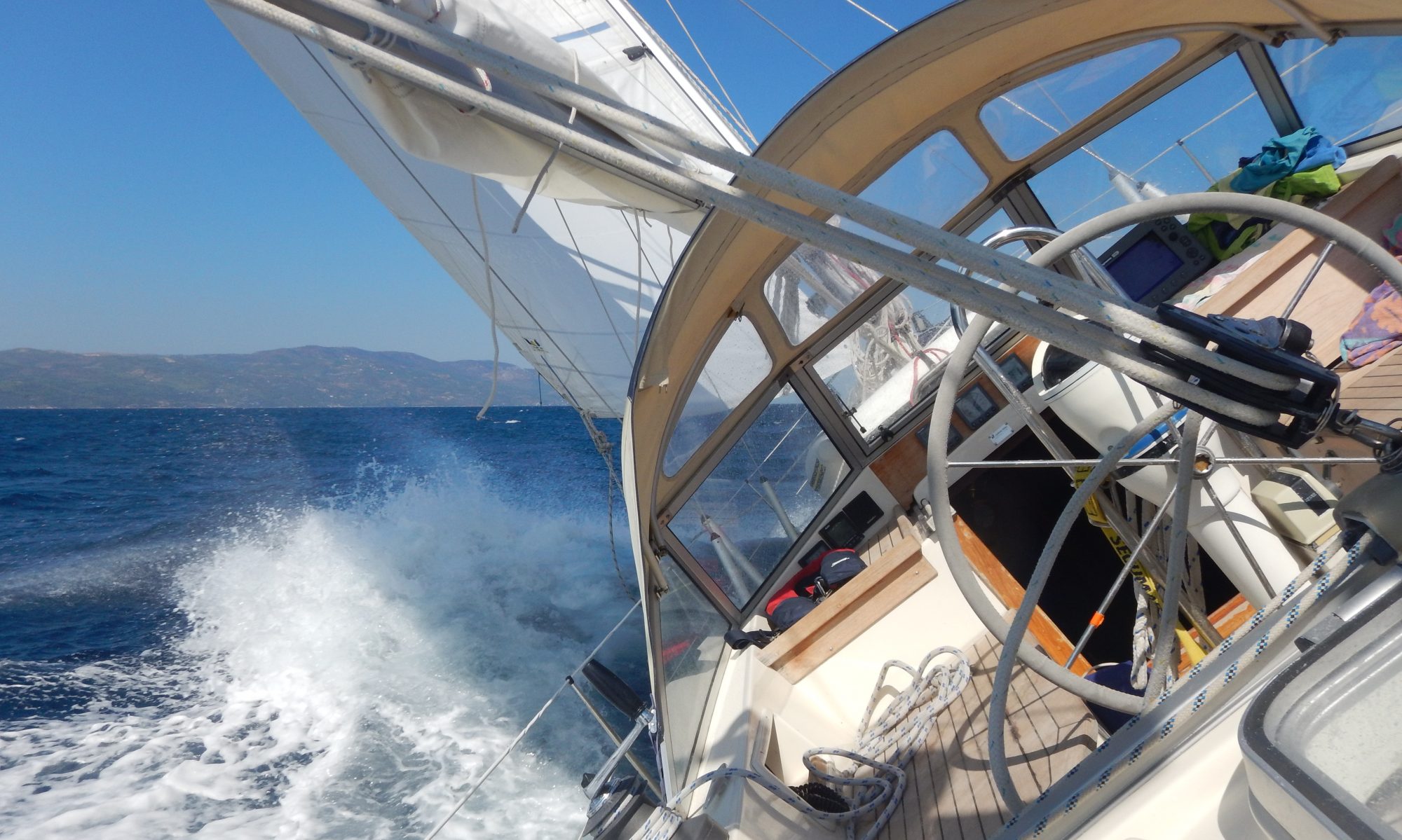
Matilda did not have enough for this summer, so I untied the lines and took her out for a little single-handed adventure to the island of Milos about a week ago. I started on Tuesday the 22nd at 6 pm and sailed through the night. A constant F5 was responsible for a fast passage to the island of Milos. 112 NM in 19 hours. I spent the next day exploring the island on a scooter. Since I wanted to be back on Monday next week, I left again on Friday in the morning ignoring the other sailor’s warnings because of the bad weather (the forecast was N F7). It was a relatively rough close hauled passage to Poros which I reached about 12 hours later. Average wave height was about 1.5m but some waves were double that height. The next day on the way to Cap Sounion the conditions were similar. I anchored in the bay underneeth Poseidon’s temple at Cap Sounion. The wind increased during the night and it was blowing at min F7 in the morning. After lifting the anchor, I rounded the cape and headed north into Makronisos channel which I believe was a mistake. Course and wind were both N and it was now blowing at F8. Because of the very steep waves, I was just making under 3 knots whilst running under engine at 2400 rpm. At the north exit of Makronisos channel, the conditions worsened and the waves became bigger, steeper and very confused. It was almost impossible to keep the boat on course and I was seriously considering turning back and going into Lavrion harbour for shelter. Conditions became better after a while and I finally decided to proceed. I arrived in Almyropotamos in the evening. It is amazing how you get used to the situation but I learned that it does not really make sense to fight against the weather in such conditions. If something goes wrong you may have a serious problem, especially if you are sailing solo. Anyway, the last day was perfect sailing at F5 and a moderate sea state and compensated for the “punishment” of the previous day.
I compiled a little video for those interrested: